The installation and commissioning of the 200KW inverter of a water plant in Kengzi was completed
In a waterworks in the eastern area of Shenzhen, the No. 1 pump is sent back to the pump using frequency conversion control, the operation mode is frequency conversion and constant pressure operation, the target outlet pressure value is set, and the automatic constant pressure frequency regulation operation.
The original frequency conversion control cabinet has a long service life, and the frequency converter suddenly fails, which is a frequency converter failure after the on-site inspection of the technicians of Huizhou Kenfulai Pump Company. Considering that the service life of this frequency conversion control cabinet has reached 15 years, it has reached the normal service life of the frequency converter, and the maintenance value is not large, so it is recommended that the user replace the old frequency conversion control cabinet.
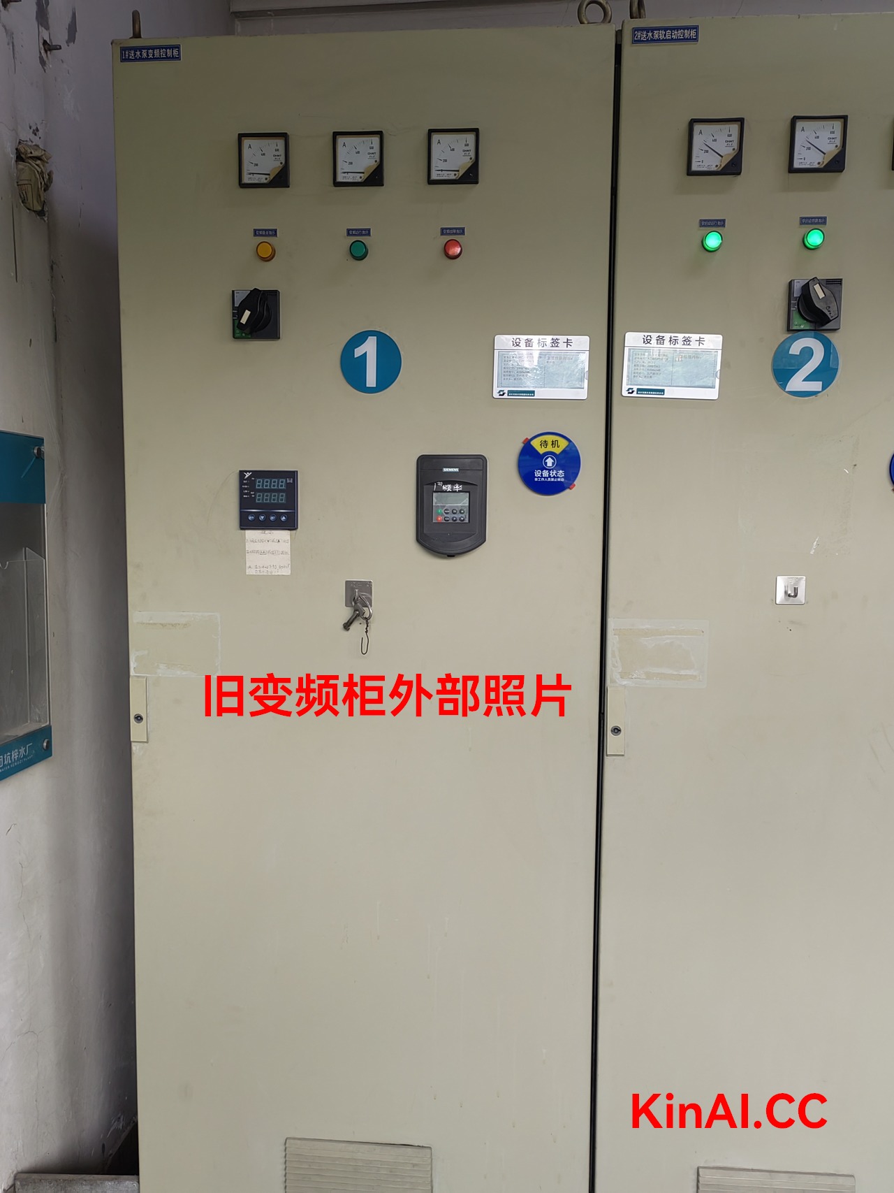
The picture above shows the current old frequency conversion control cabinet, you can see that next to the inverter display panel, a PID controller is installed, and the way to adjust the motor operating frequency is controlled by an external PID controller. The disadvantage of using an external PID controller is that the overshoot problem is more prominent, the speed of the pump changes greatly, and the system stability is poor, which is not conducive to prolonging the service life of rotating equipment.
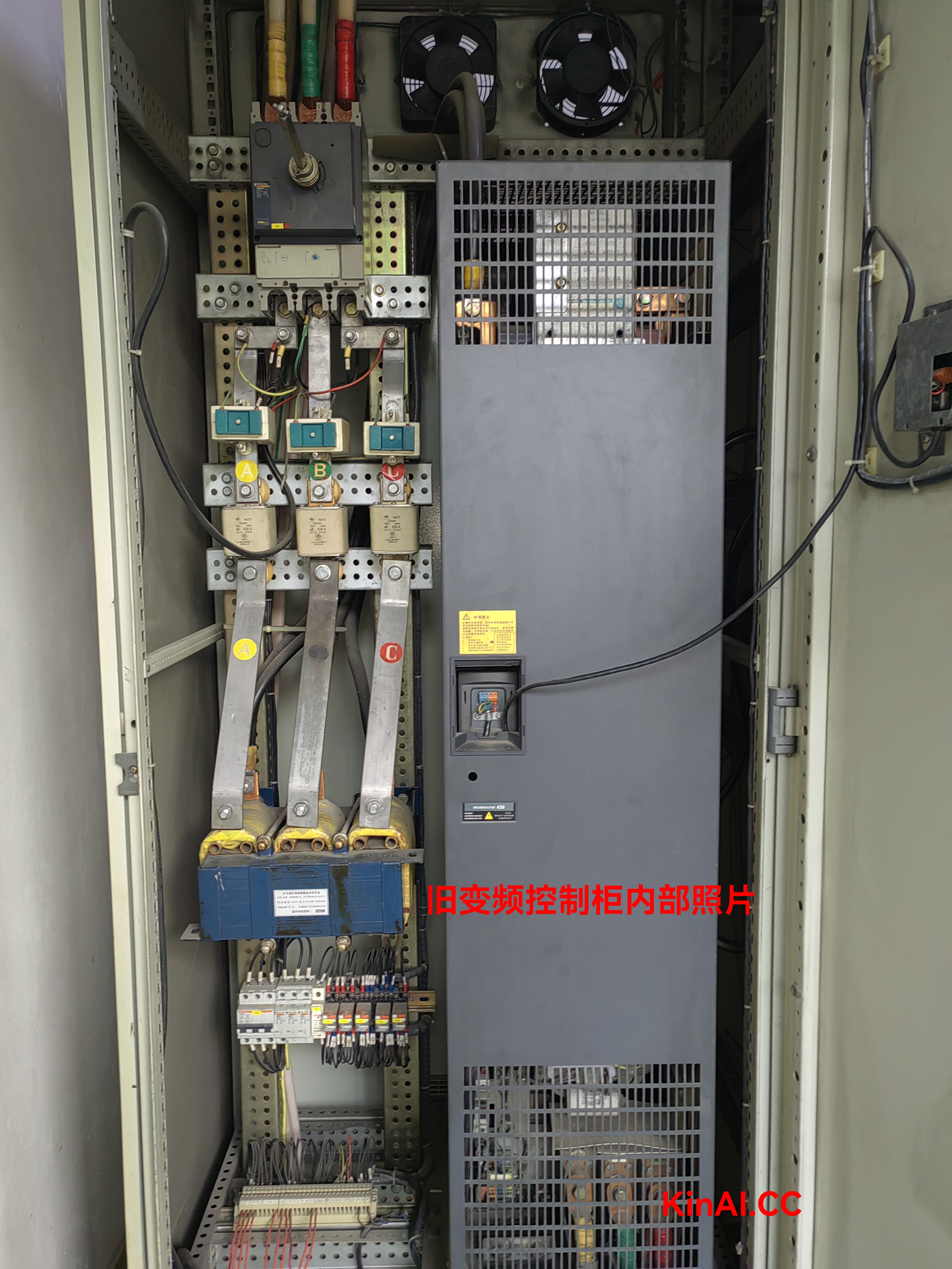
The picture above shows the layout of electrical components in the current old inverter control cabinet.
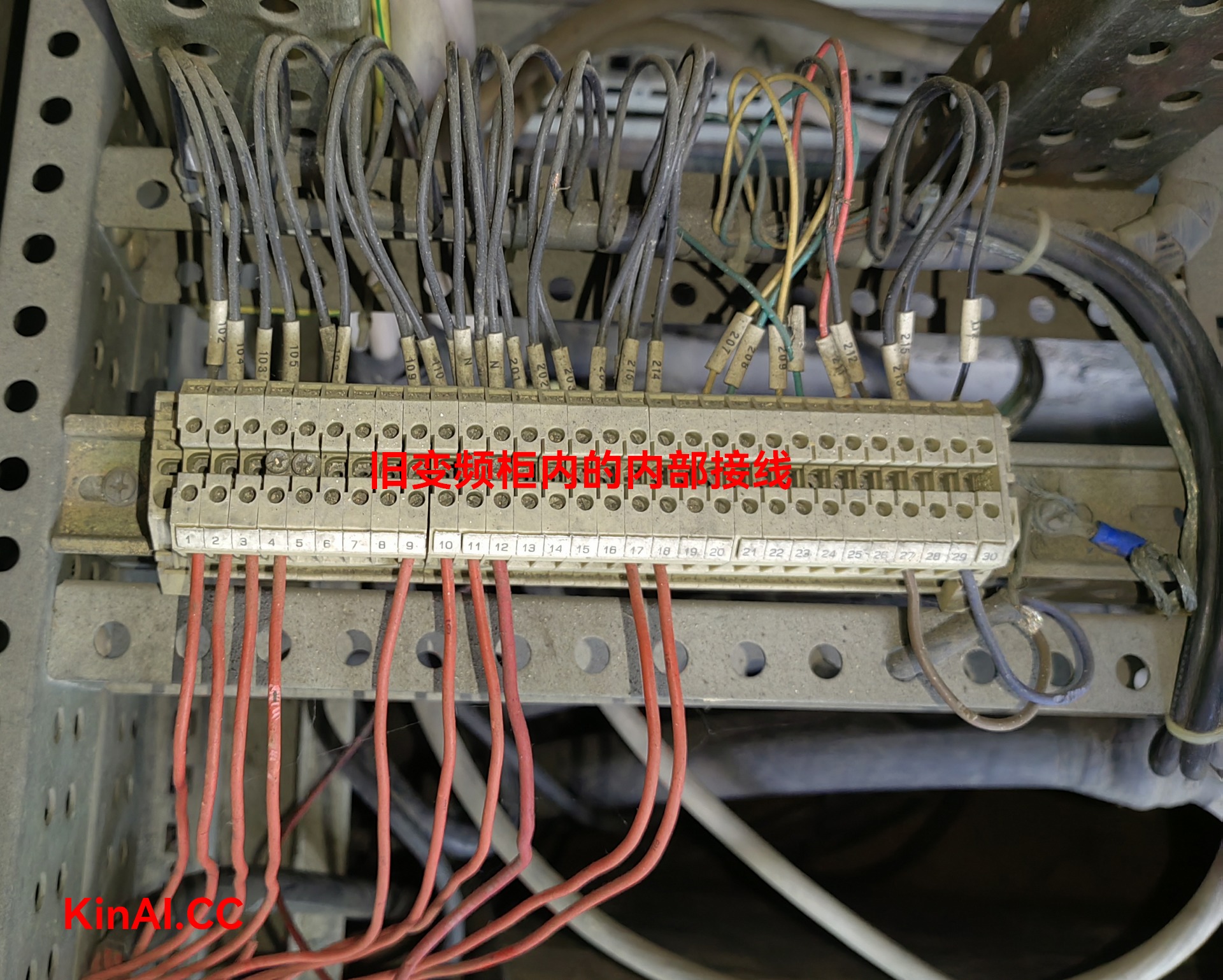
The picture above is the control loop wiring in the old frequency conversion control cabinet, the red control line is connected to the control box next to the pump unit (also known as the next control box), through inspection, it is found that the red line here actually includes 220V power supply, power supply to the indicator light of the side box.
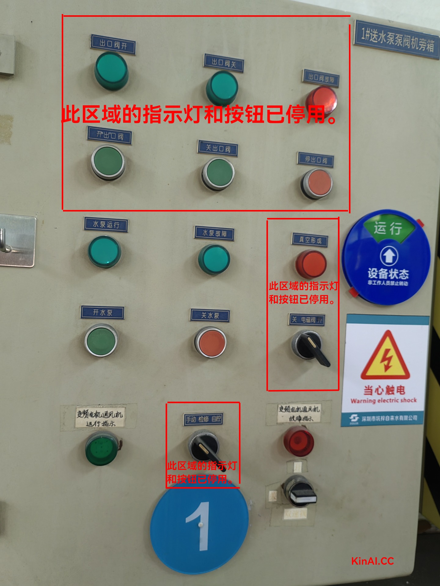
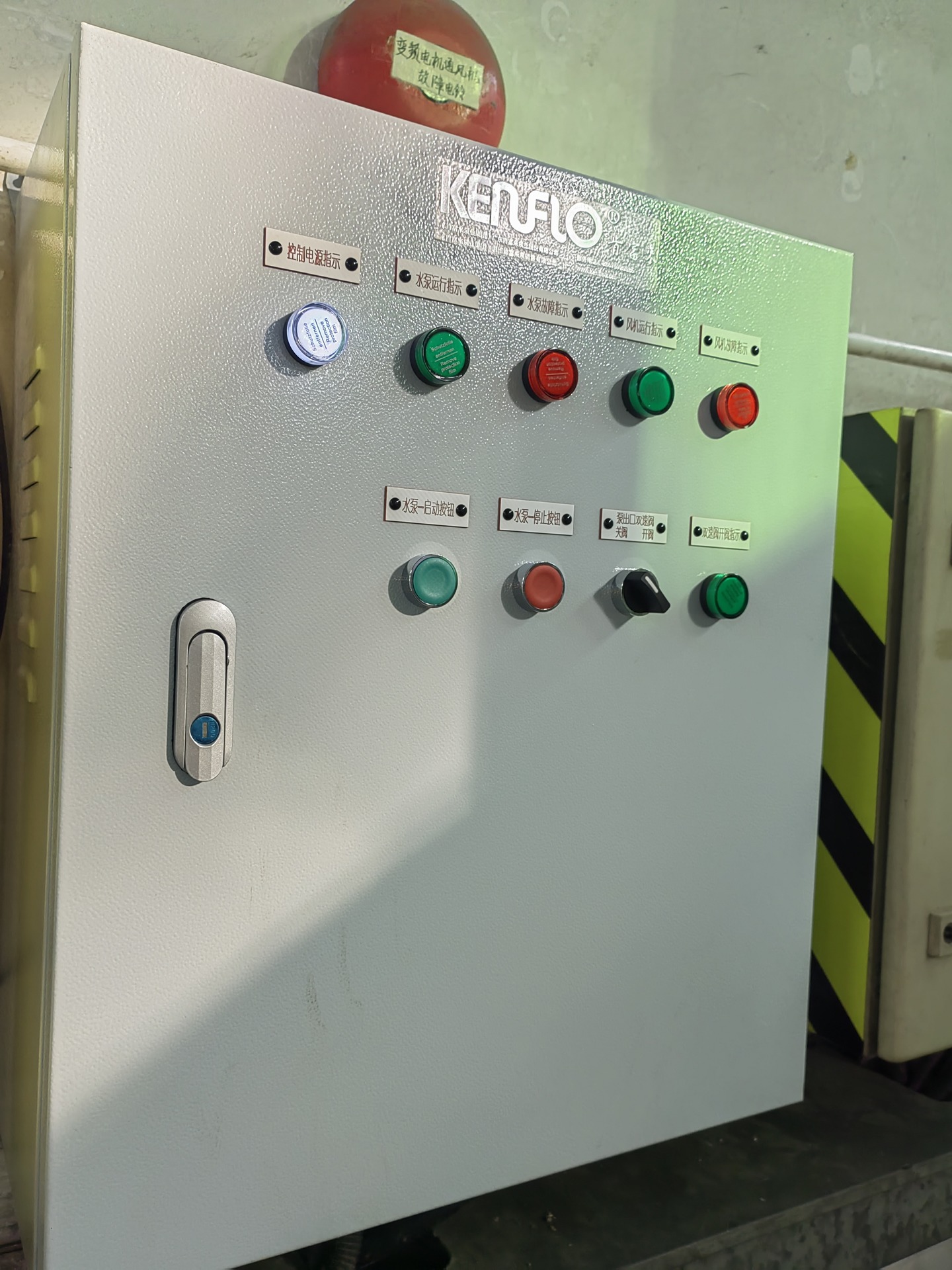
The picture above is the exterior photo of the side box next to the pump unit, which has been modified many times, but each modification is aimed at meeting the most basic functions, and the internal wiring is chaotic. Moreover, most of the wiring, electrical components, operating buttons, and indicator lights on the side box have been out of service for many years, and the related equipment has been removed.
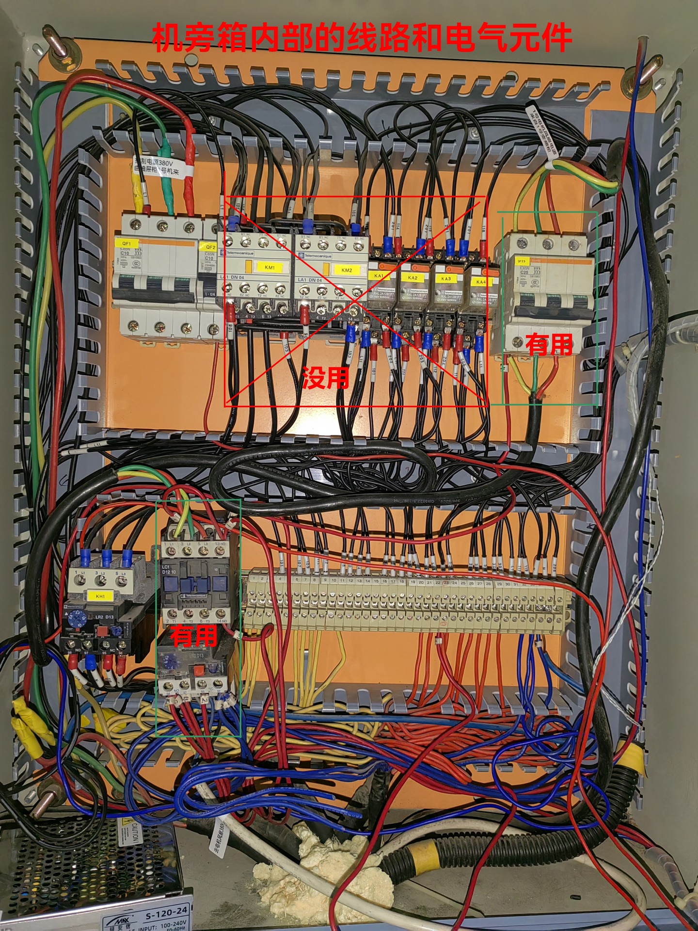
The picture above shows the internal wiring and electrical components of the side box, after inspection, most of the electrical components in the side box have been deactivated, and the internal wiring is more chaotic.
The old machine side box has a total of 3 power supplies, which are as follows:
(1) The main circuit breaker in the upper left corner, the power supply comes from the chest of drawers, it is a 380V three-phase power supply, 5-wire system, with 1 zero wire and 1 ground wire. Among them, the zero wire and ground wire are connected to the zero wire copper bar and ground wire copper bar of the drawer cabinet. However, it should be noted that this circuit breaker is not used, and the only thing that supplies power to the control loop of this side box is the L1 control power line connected in parallel above the circuit breaker. After inspection, the L1 line finally provided power for the 220V to 24V switching power supply of the two-speed valve. In other words, the normal use of the two-speed valve must rely on L1, and must rely on the power supply of the chest of drawers.
(2) The circuit breaker (green frame) in the upper right corner is the power cord of the inverter motor fan. It is 380V. It is connected to the fan contactor (green box).
(3) The coil of the fan contactor and the power supply of the indicator light are provided by the red No. 1 line in the lower right corner and connected to the frequency conversion control cabinet.
That is to say, in this small side box, there are 3 different power supplies, any of which fails or is accidentally powered off, which will cause the side box to work abnormally. More seriously, if the control of the solenoid valve fails (the two-speed valve cannot be closed) and the pump stops, it will cause water to flow back from the outlet pipe to the inlet pool, resulting in the pump in parallel running at 0 head, which will cause other parallel pumps to have the problem of excessive power and tripping, resulting in water supply interruption.
In this project, the original plan was to replace the frequency conversion control cabinet, after the installation of the frequency conversion control cabinet, KENFLO on-site construction personnel carried out line inspection and wiring preparation for the side box, and after analyzing the problems existing in the side box, they urgently processed and made a new side box to improve the reliability of the side box.
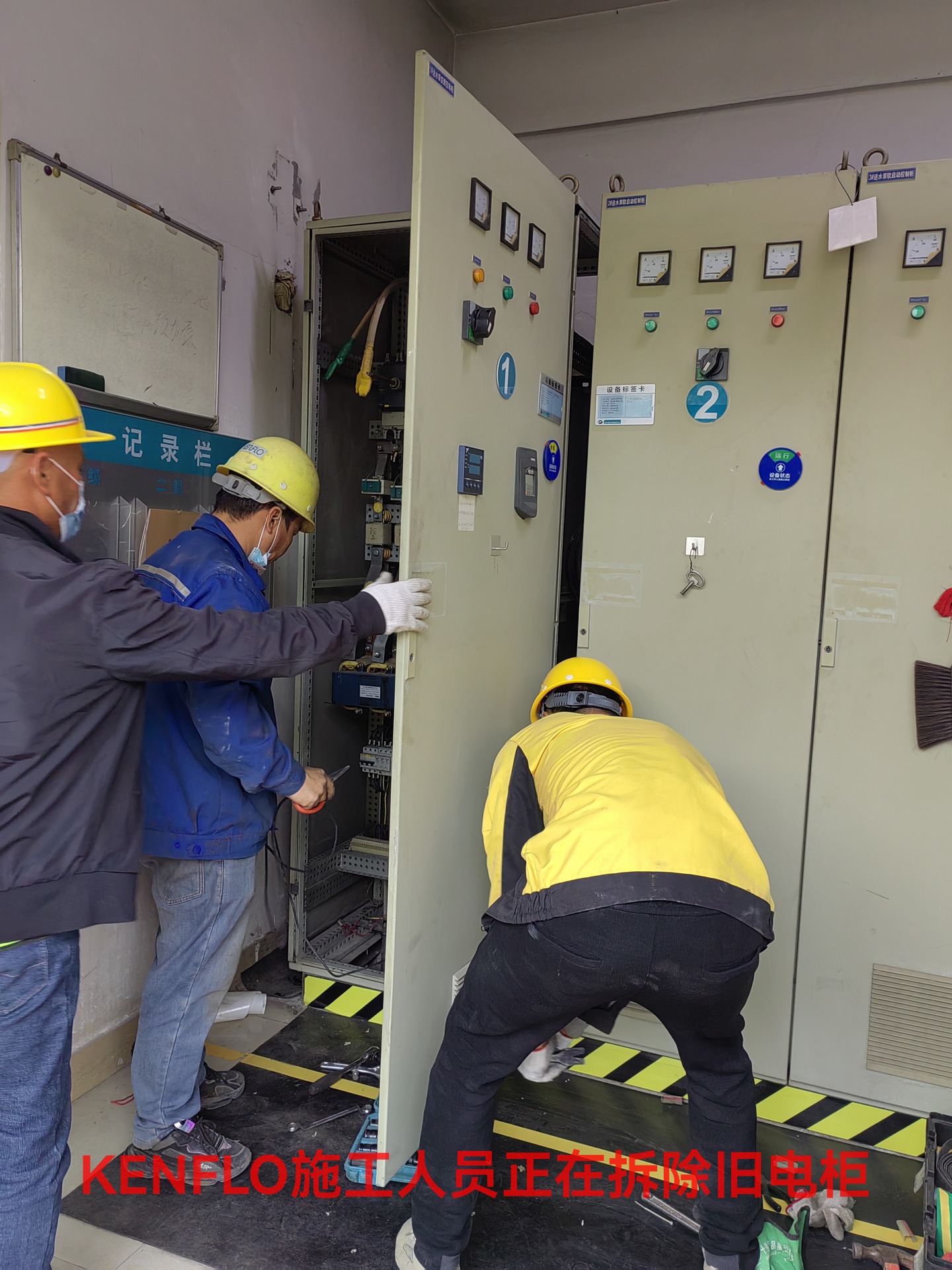
The picture above shows Kenfulai construction workers dismantling old electrical cabinets. First, the connected power cable, control cable, and then the electric control cabinet were removed.
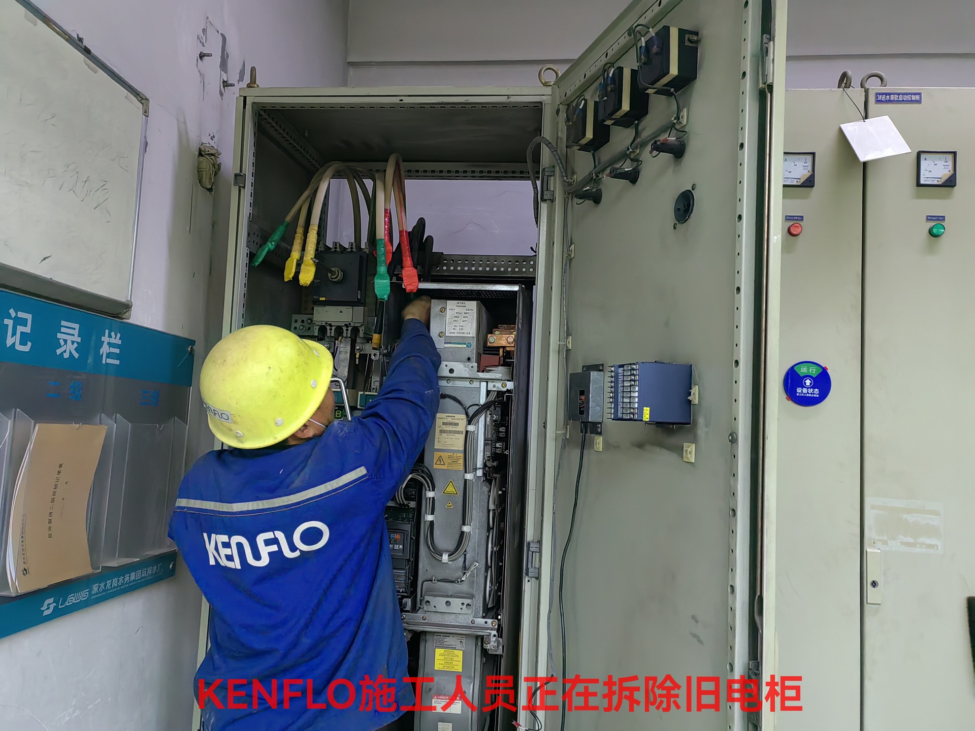
In the process of dismantling the old electrical cabinet, each cable is insulated and the cable is marked. Considering that the cable still needs to be pulled out of the old electrical cabinet, and then penetrated into the new electric cabinet, in the process of threading, in order to prevent the cable head from touching the live electric cabinet next to it, all are insulated protection.
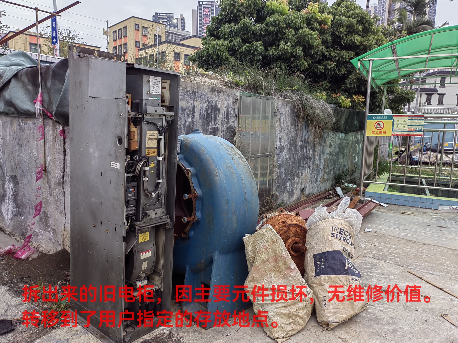
And the dismantled electric cabinet is placed in the place specified by the user.
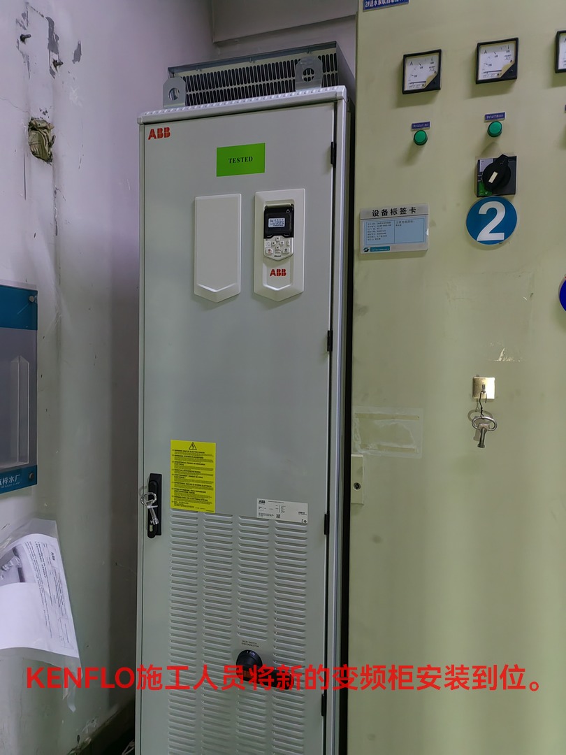
KENFLO construction crews put the new inverter control cabinet in place. This frequency conversion control cabinet adopts ABB brand original integrated cabinet, you can see that the original cabinet is not installed on the operation button, indicator light, nor installed secondary control line, need to go to the site, according to the user's operation requirements, the site installation of secondary control loop and operation button.
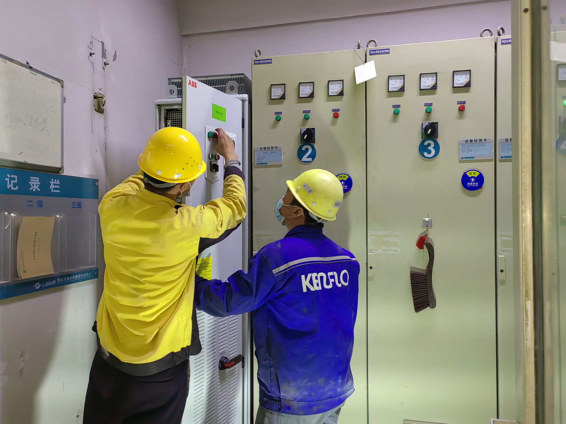
The picture above shows KENFLO construction personnel on site to open holes in the operation panel, install indicator lights, install operation buttons and knobs, etc.
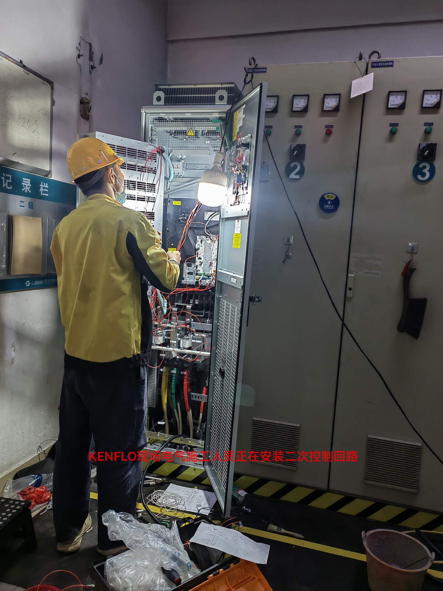
After installing the operation panel, KENFLO electrical construction personnel worked overtime to install the secondary control loop and carry out on-site wiring according to KENFLO's design drawings.

The picture above is an internal photo of the inverter cabinet after the secondary control loop and electrical components have been installed. All cables are clearly marked, as are the main electrical components, which is very beneficial for future maintenance and overhaul.
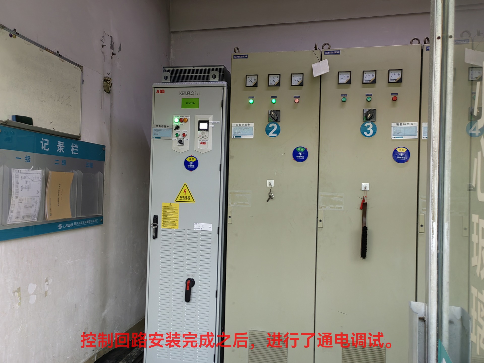
Above, the frequency conversion control cabinet after installation.
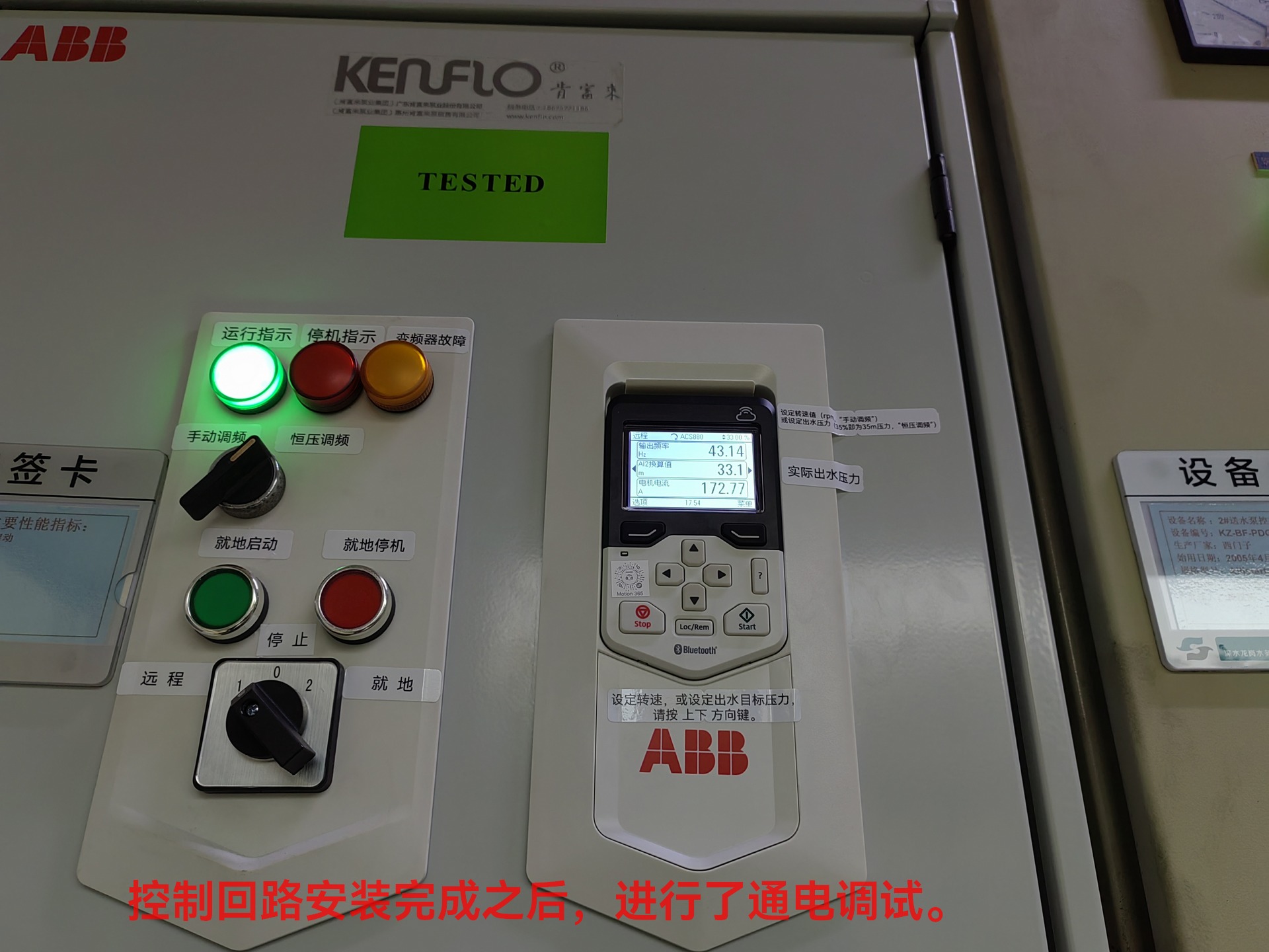
We have designed two operating modes for this integrated inverter control cabinet:
(1) Manual FM operation. In this mode, the output frequency of the inverter is manually given by the user and frequency modulation is not performed automatically. Because considering that the user's several pumps running in parallel, a total of two pumps are equipped with frequency converters, in the same system, if both pumps are automatically converted, it is easy to cause mutual interference of frequency modulation programs. Therefore, the manual frequency modulation mode is designed, which can also be called fixed frequency operation mode, and the user can set this frequency conversion control cabinet to a fixed frequency operation through the knob, and let another frequency conversion pump in parallel automatically convert the frequency.
(2) Automatic constant voltage frequency conversion operation. In this mode, the PID process control in the inverter automatically adjusts the output frequency of the inverter according to the feedback of the outlet main pressure value to maintain a constant outlet pressure. PID process control ratio, integration, differentiation and other parameters, we took a preliminary setting, trial operation and observation of the adjustment effect and system oscillation degree, and then carried out a second fine-tuning. The actual operation effect is better, the outlet pressure and operating frequency are stable, and the fluctuation of the operating frequency is small, and the operating frequency is stable most of the time, which is of positive significance for extending the service life of the motor and pump.
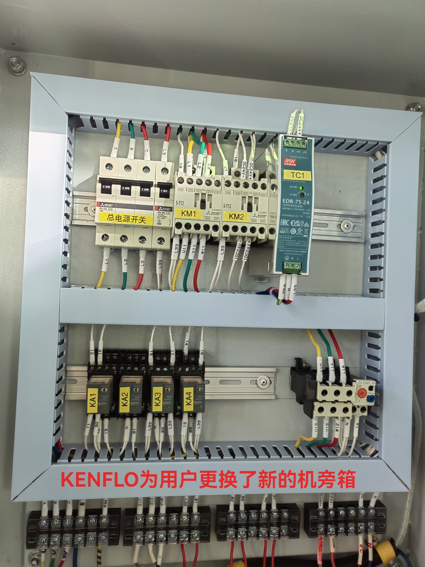
At the same time, considering the confusion of the electrical components and control lines in the old side box, this project replaced the new side box for users, the internal electrical components and wiring layout are neat and beautiful, the control logic is clear, and the lines and electrical components are clearly marked.
After debugging and trial operation, the newly installed frequency conversion control cabinet and side box are operating normally, the PID process control parameters are reasonably designed, the system adjustment speed is fast and there is no vibration phenomenon, and the pump unit runs stably.
共有 0 条评论